8.3.1. Spherical wavefront.
Download Python script: SphericalWavefront.py

Christiaan Huygens (Den Haag, 1629 – 1695)
In this experiment a spherical wavefront is made with a screen containing a small hole. If the diameter, \(d\), of the hole is small enough there will be a spherical wave at some distance behind the screen.
You can check for a spherical wave by measuring the irradiance at the optical axis as a function of the distance, \(z\).
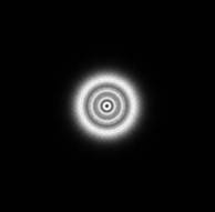
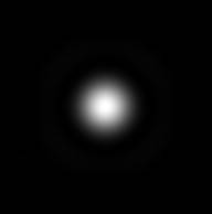
Just behind the hole, the diameter of the spot is about equal to the diameter of the hole. When the distance, \(z\), increases the spot irradiance distribution will be a set of concentric rings with alternating maximum and minimum irradiance at the axis. At some distance, called the Rayleigh length, the pattern will change into a more uniform distribution. For distances shorter than the Rayleigh length the diffraction is called Fresnel or near-field diffraction and for larger distances Fraunhofer or far-field diffraction. When \(z\) is much larger than the Rayleigh length, the beam can be approximated near axis as a spherical wave.
The Rayleigh length is also defined as the distance at which the area of the spot doubles and depends on the hole diameter and the wavelength of the light:
with \(A\) the hole area. Another indicator of Fresnel- or Fraunhofer diffraction is the Fresnel number, given by:
The Fresnel number gives the number of so-called Fresnel half-wavelength zones ‘seen’ by the observer. If the number of zones is even, a minimum irradiance can be observed on axis. A maximum occurs if \(N_F\) is odd. (The Fresnel and Fraunhofer diffraction theory will be introduced in experiment 6, Fresnel Diffraction. Also see Pedrotti chapter 13). Depending on the required accuracy the minimum distance from the hole must be some factor times \(Z_R\). A factor 100-200 is often chosen, for this exercise a factor 10 will due.
Fresnel or near-field diffraction
Fraunhofer or far-field diffraction
8.3.1.1. Irradiance dependency of a spherical wavefront.
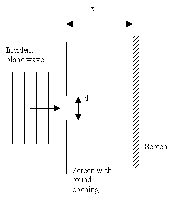
Setup of the experiment. A spherical wave is made by illuminating a small hole in a screen.
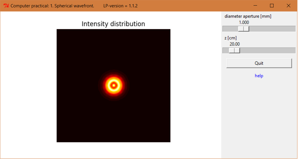
Screenshot of the spherical wavefront experiment.
Download Python script: SphericalWavefront.py
Write down the expression for the irradiance distribution as a function of the propagation distance, \(z\), for a spherical electro-magnetic wave.
Measure the irradiance at the optical axis as a function of \(z\) for a small (\(d \approx 0.15 mm\)) and a large (\(d \approx 0.65 mm\)) hole diameter.
Plot the irradiance as a function of \(z\) for both hole diameters. Plot such that you obtain a straight line. (In general, the benefit of a straight line is that one can easily judge whether or not the theory is valid and also in which range of parameters the theory is valid. Furthermore, values of theoretical parameters can, in general, be obtained from the slope of the line and the axis-cut)
Determine, for both cases, the range of \(z\) for which the beam can be considered as spherical. Compare this range with the Rayleigh length.
8.3.1.2. Questions about the spherical wavefront.
You should be able to answer the following questions:
What happens if the diameter of the hole is too large and/or if the screen is too close to the hole?
What is the influence of the wavelength?
Why did you plot your results as a straight line?
You should be able to answer the questions below at the end of the course (Try it now if you can!)
What type of diffraction do you see just behind the hole and what type far away? What kind of diffraction are we dealing with for spherical waves?
What is meant with the “Fresnel number” and “Rayleigh length”. When is the Fresnel number equal to one?
What are Fresnel half-wavelength zones? What is the relation of these zones with the Fresnel number?
A diffraction pattern can be considered as an interference phenomena. Why?
Under some conditions the hole can be used as some kind of camera lens, the so-called pin-hole camera or “camera obscura”. What condition must be fulfilled and what are the advantages and disadvantages of such a camera compared to the common camera with a normal lens.